


Next: Solid Body Rotation
Up: Testing by Comparison with
Previous: The LVG case
A Detailed Comparison with a 1-D Model
The ability of this version of the program to include rotation of the cloud is the first
modification that cannot be compared with the original version. However there is a modification to
the original program by Buckley that allows solid body rotation to be simulated. It does this by switching to a
rotating frame of reference for the output calculations. This enables a first approximation to be made for a
rotating cloud without all the extra complications of a full 2-D model since the first part of the program can
remain untouched. It is therefore possible to use his results as a test of the rotational section of the
ASTRA program since it deals with solid body rotation in exactly the same way as it does with all other types
of rotation.
Model line profiles of a collapsing cloud (taken from Krügel & Chini [18])
[l]
![\includegraphics[scale=0.35]{krug1.eps}](img1058.gif) The problem with using Buckley's model to do the testing with is that it uses the same core sections as this program
- ie. both are based on the STEN program. It would therefore first be useful to test the ASTRA program against a
completely independent model. In order to simultaneously make comparisons with Buckley's model the same source will
be used for making comparisons as he used for testing his modified version, namely a paper by Krügel & Chini [18]. In this they use
a microturbulent modelling program
The problem with using Buckley's model to do the testing with is that it uses the same core sections as this program
- ie. both are based on the STEN program. It would therefore first be useful to test the ASTRA program against a
completely independent model. In order to simultaneously make comparisons with Buckley's model the same source will
be used for making comparisons as he used for testing his modified version, namely a paper by Krügel & Chini [18]. In this they use
a microturbulent modelling program
(that is a program that "assumes the mean free path of the photons is
much larger than the scale length of the turbulent motions" [18]) to produce simulated line profiles
for CS in a cloud that has similar properties to the class 0 object HH24MMS. Their results are presented in
figure 5.13 for various transitions at different beam sizes.
The parameters they used for their cloud were


Model line profiles of the same cloud as in figure 5.13 from Buckley's model (taken
from [7]).
[l]
![\includegraphics[scale=0.35]{krugbuk.eps}](img1064.gif) This is a good model to start testing as, although it has quite a steep gradient for the hydrogen
density towards the centre of the cloud (
This is a good model to start testing as, although it has quite a steep gradient for the hydrogen
density towards the centre of the cloud (
 ), the temperature is much higher on the outside of the
cloud. This means the centre of the cloud does not play such an important role in the shape of the line profiles as
it would if it were hot. The problem for a model with a hot centre is that it subtends only a small angle and can
therefore easily be missed by the lines of sight originating in rings further out in the cloud. This is therefore a
fairly simple first test. Figure 5.14 shows the output for the same cloud from Buckley's model. It can
be seen that the line shapes are in good agreement, although in places Buckley's model is up to 20% weaker than the
Krügel & Chini version (the biggest differences are in the secondary peaks of the
 and
and
 transitions).
These line profiles can now be reproduced using the ASTRA program and are presented in figure 5.15. It
can be seen that again the line shapes are very close to those in figure 5.13 but as with Buckley's
version the line intensities are not the same. The discrepancies are however different from those in
Buckley's version. Here the line intensity for the smaller beam sizes is clearly stronger by about 20%. A
possible explanation is that for these lines  which is a more difficult case to deal with as there is
no saturation. It may simply be caused by the model descriptions not being exactly the same.
As mentioned above, the Krügel & Chini model is fairly easy to model as it does not involve dealing with a hot
cloud core. There is, however, a model presented by Buckley [7] which does have a hot core so this
will be used for the next test.
The parameters given by Buckley that will be used here were a cloud of radius 0.047 pc at a distance
of 200 pc from a JCMT like telescope with internal parameters given by:
Note the final equation is just a ratio and hence has no units. Unfortunately Buckley does not completely specify the
model parameters being used: missing from this list are the inner cutoff (the radius within
which all parameters are held constant) as well as the shell distribution used. Nonetheless it is possible to deduce
approximately what these should be by trying various parameters and seeing how well the resulting line profiles match those
given by Buckley. Figure 5.16 below is a copy from his thesis of the results his program gave. These results are
for a non-rotating cloud which can be used as an initial check that the
parameters given above have been correctly mapped onto the grid of disk/cylinder intersections. In all four diagrams the solid
line represents the output of the model described above with a relative abundance of
 for the molecules. In
the HCO+ diagrams the dashed line is the output for H
 CO+ with exactly the same parameters as for HCO+ except with an
abundance a factor of 60 less that for the main isotope (and also a very small correction for the different frequency of the
transition).
![\includegraphics[scale=1]{bukmodel.eps}](img1078.gif) Output of Buckley's model results (taken from [7])
Output of Buckley's model results (taken from [7])
HCO+(3
 2) output for various different cut-off values:
| |
dotted |
0.0001pc |
| |
solid |
0.001pc |
| |
dashed |
0.002pc |
| |
dot-dash |
0.005pc |
[l]
![\includegraphics[scale=1]{bukm1.eps}](img1079.gif)
Figure 5.17 shows output for a variety of different cut-off values. It can be seen that, as expected, the smaller the
inner cut-off the wider the lines since placing the cut-off further in allows the velocity to rise to higher values. It can be
seen that the line widths approximately agree with those in figure 5.16 when the cut-off is placed at 0.001pc
(the solid line). It will therefore be assumed that Buckley was using a cut-off of 0.001pc. Within this cut-off all the
parameters are held constant at the values that they had at the 0.001pc position. In order to avoid problems at the centre
of the cloud a very small inner ring is inserted at 0.00001pc within which the collapse velocity declines linearly to zero at
the centre. This provides a smooth switch over from positive to negative velocity for the program to deal with without having a
significant effect on the output.
HCO+(3
 2) output for various different ring numbers:
| |
dashed |
6 12 12 |
| |
dot-dash |
12 24 24 |
| |
solid |
18 36 36 |
| |
dotted |
32 64 64 |
[l]
![\includegraphics[scale=1]{bukm2.eps}](img1080.gif) It is more difficult to
establish what shell distribution was being used. Buckley's program takes as input the inner cut-off, the outer cloud radius and
the number of shells required and then distributes the shells in a logarithmic manner (ie. a heavy weighting of shell numbers in
the inner part of the cloud with fewer shells further out - the justification being that there are rapid changes in the inner
part of the cloud but only slow changes further out). Ideally of course a very large number of evenly distributed shells would be
used, however, the length of time a model takes to run is strongly dependent on the number of shells. This
dependence is
even stronger for the ASTRA program as being a 2-D model doubling the number of cylinders entails doubling the number of disks
(in order to simulate a spherical cloud - it would not necessarily need equal numbers or disks and cylinders for other types of
model). This means the number of rings goes up with the square of the number of cylinders. Figure 5.18 shows output
for models with increasing numbers of rings. It can be seen that only the models with a very small number of rings cause the
line profiles to deviate. There appears to be no advantage in running very large models for this particular type of cloud. The
table below shows the run times for these 4 models5.1 which
demonstrates the increasing time penalty for larger models. As an approximate rule
It is more difficult to
establish what shell distribution was being used. Buckley's program takes as input the inner cut-off, the outer cloud radius and
the number of shells required and then distributes the shells in a logarithmic manner (ie. a heavy weighting of shell numbers in
the inner part of the cloud with fewer shells further out - the justification being that there are rapid changes in the inner
part of the cloud but only slow changes further out). Ideally of course a very large number of evenly distributed shells would be
used, however, the length of time a model takes to run is strongly dependent on the number of shells. This
dependence is
even stronger for the ASTRA program as being a 2-D model doubling the number of cylinders entails doubling the number of disks
(in order to simulate a spherical cloud - it would not necessarily need equal numbers or disks and cylinders for other types of
model). This means the number of rings goes up with the square of the number of cylinders. Figure 5.18 shows output
for models with increasing numbers of rings. It can be seen that only the models with a very small number of rings cause the
line profiles to deviate. There appears to be no advantage in running very large models for this particular type of cloud. The
table below shows the run times for these 4 models5.1 which
demonstrates the increasing time penalty for larger models. As an approximate rule
 where
where  is the time taken and
 &
&
 are the number of cylinders and disks
present in the cloud. In other words, as might be expected the time taken to run a model increases approximately
linearly with the number of rings in the cloud.
| Model size |
Run time |
(no. of cyls  no. of disks)
 |
(minutes) |
6 12 12 |
2.8 |
12 24 24 |
9.6 |
18 36 36 |
11.8 |
32 64 64 |
83 |
Also of interest is how the line profiles vary with the way the rings are distributed in the cloud. Thus far all models have
been run with an  distribution of cylinders and disks (see equation 4.58 and the surrounding
text on page
 ![[*]](icons/cross_ref_motif.gif) for an explanation of this). Figure 5.19 shows the line profiles for
models with an
for an explanation of this). Figure 5.19 shows the line profiles for
models with an  (ie. evenly spaced)
and an
  distribution (ie. weighted very heavily towards the centre). It can be seen that by not weighting the rings towards
the centre the line profile is made narrower. However, figure 5.20 shows this to be incorrect as increasing the number
of rings in the cloud (but still using a linear distribution) widens the line profile back towards that given by the weighted
distribution. This confirms the validity of using a weighted distribution, at least for this type of cloud.
In view of the above it would now seem valid to proceed using the 18 36 ring model with an inner cut-off at 0.001pc which
should be modelling a very similar cloud to that used by Buckley. The actual cylinder distribution used was as
shown below (the numbers are taken directly from the input file and are in parsecs):
                0.00001                         0.01084
                0.0001                          0.01401
                0.0005                          0.0176
                0.00071                         0.02161
                0.00134                         0.02604
                0.0024                          0.0309
                0.00387                         0.03617
                0.0057                          0.04187
                0.0081                          0.048
The same numbers were also used for the disk distribution. These were produced by using the astra.tcl interface
to produce 16 cylinders from 0.0005 pc outwards with an  distribution. The inner two cylinders were then added
by hand to enable better modelling of the various different inner cut-offs and to provide the smooth cross over at
the centre as previously described.
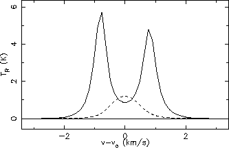
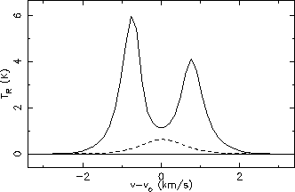
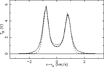
Line profiles for HCO+ (solid) and H

CO+ (dashed), 3

2 (left) and 4

3
(right)
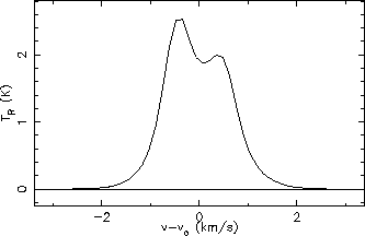
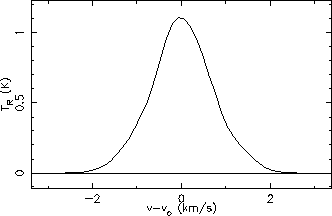
Line profiles for CS 5

4 (left) and 7

6 (right)
Comparing the line profiles in figures 5.21 & 5.22 with the versions produced by Buckley in
figure 5.16 (page ![[*]](icons/cross_ref_motif.gif) ) shows that there is good agreement for all the line
shapes. The only slight discrepancy is in the relative intensities of the
) shows that there is good agreement for all the line
shapes. The only slight discrepancy is in the relative intensities of the
 and
and
 HCO+
transitions. The
 transition is slightly stronger than the
 transition here whereas
the situation is the opposite in Buckley's model output. It is possible that this is due to slightly different
beamsizes being used as Buckley only says he is simulating output from the JCMT without saying exactly what
beamsize he used. The beamsize used here was calculated from the formulas given on the JCMT web page and were
18.3
 and 13.6
 for the 267.5 GHz
 and the 356.7 GHz
 transitions
respectively5.2.
Figures 5.23 & 5.24 show the line profiles for exactly the same model parameters except
with a variation in the relative abundance of the HCO+ and CS molecules respectively. These can be compared with
the line profiles generated by Buckley which are shown in figure 5.25. It can be seen here that whilst
the CS lines are virtually identical for all abundances the slight differences in the
 HCO+
transition mentioned in the above paragraph have been accentuated for the higher abundance of
 but
have been decreased for the lower abundances (the solid line is the abundance used in
figures 5.21 &- 5.22). There are several possible explanations for this. One is that it is
caused by differences in the collision coefficients used as there are several different sources for the HCO+
coefficients but he is known to be using the same coefficients for CS. However, since this cloud is radiation
dominated it would seem that collisions between molecules should only play a small role in deciding the line
profiles. It is also possible that the aforementioned unknown factor with the beamsize that Buckley used could be
causing this although it might be expected that this would affect the CS profiles as well (using a beamsize of 15
 reduces the peak of the
 HCO+ line by
 K). Probably the most likely cause is
that the distribution of parameters in the shells/rings is not quite the same. In addition to the obvious point
that these will not be exactly the same since the 2-D simulation of the 1-D spherical symmetry is not perfect one
there are also differences in the way the parameters are assigned to the rings. In the STEN program the value of a
parameter is calculated for the outer edge of a shell and then held constant at that value across the whole shell.
For the ASTRA program it is calculated at the four corners of a ring and then averaged to form the value for that
ring. These differences may also cause a small change in the line profile, however, these differences should
become smaller for models with larger numbers of rings or shells. A final possibility is that since the
discrepancy only shows up at high optical depths there is some problem with either this program or Buckley's
program in the calculation of line profiles where the optical depths are very high. If this were the case though
more problems might be expected with the
 line since it has a higher optical depth than the
 line.
line.
![\includegraphics[scale=0.57]{buk2.eps}](img1098.gif) Output of Buckley's model results (taken from [7]) for different abundances
Output of Buckley's model results (taken from [7]) for different abundances
The advantages of using this particular model cloud to test the program are that it has fairly sharp changes
in the parameter values towards the centre and also produces optically thick line profiles which are much more
difficult to model than optical thin lines. This makes it more likely that problems will show up modelling this
cloud. It is therefore also a good model to use to investigate the behaviour of the program when some of the other
modelling parameters are altered. The most important two parameters are firstly the number of lines of sight used
in each ring to calculate the radiation field on that ring and secondly the number of lines of sight used in the
gridding routine to model the telescope beam. Both of these parameters follow the usual rule that larger numbers
give a more accurate result but also increase the length of time needed to run a model. It can be seen from
figures 5.26 & 5.27 that even for this kind of model that has rapid changes towards
the centre of the cloud it is not necessary to have large number of lines of sight. Even the extremely basic
 line profile is very similar to the
  model.
  corresponds to just 6 lines of sight
(ie. 4 around the 'equator', one straight up and one straight down) in comparison to
  which corresponds
to 332 lines of sight. The time penalty for the larger models is huge: the
  model took 5 hours 47 mins
to run compared to the
  model which takes just 19 mins. Note that the
  model takes longer than
the
  model as it does not converge as fast and therefore needs more iterations even though each iteration
is faster. Unless otherwise stated the
  model is always the one used (this corresponds to 22 lines of
sight per ring).
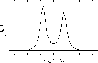
Line profiles for HCO+ 3

2 with different values of
hlines:
| dashed |
4 |
| solid |
8 |
| dot-dashed |
12 |
| dotted |
32 |
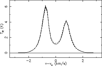
Line profiles for HCO+ 4

3 with different values of
hlines:
| dashed |
4 |
| solid |
8 |
| dot-dashed |
12 |
| dotted |
32 |
Output for different viewing angles
[l]
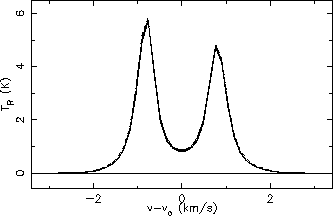 The other unique feature of the ASTRA program is the ability to change the cloud viewing angle. Clearly this is
not a useful feature for a spherically symmetric cloud. However, the spherically symmetric cloud model can be used
to check the basic working of this feature. For a spherically symmetric cloud the line profiles should be the same
no matter where they are viewed from. Figure 5.28 shows the line profiles for the cloud at 0
 ,
15
,
15 ,
30
,
30 ,
45
,
45 ,
60
,
60 ,
75
,
75 and 89.9
 .
Note that it is best to avoid
choosing exactly 90
 as this would mean the line of sight runs exactly down the centre line of the cloud
parallel to the cylinders which is a situation the geometry subroutine is not designed to handle. In
addition equation 5.28 includes the line profiles viewed from a cloud that has been inclined 45
 and
also rotated 45
 in the plane of the sky as well as output from a model that has been rotated 90
 in
the plane of the sky. See the text around figure 4.20 (page
 ![[*]](icons/cross_ref_motif.gif) ) for an
explanation of the types of rotation possible. It is clear from the figure that at least for this rather limited
test the program works correctly as the differences are no more that a few percent at most.
) for an
explanation of the types of rotation possible. It is clear from the figure that at least for this rather limited
test the program works correctly as the differences are no more that a few percent at most.


Next: Solid Body Rotation
Up: Testing by Comparison with
Previous: The LVG case
1999-04-12
![\includegraphics[scale=0.35]{krug1.eps}](img1058.gif) The problem with using Buckley's model to do the testing with is that it uses the same core sections as this program
- ie. both are based on the STEN program. It would therefore first be useful to test the ASTRA program against a
completely independent model. In order to simultaneously make comparisons with Buckley's model the same source will
be used for making comparisons as he used for testing his modified version, namely a paper by Krügel & Chini [18]. In this they use
a microturbulent modelling program
The problem with using Buckley's model to do the testing with is that it uses the same core sections as this program
- ie. both are based on the STEN program. It would therefore first be useful to test the ASTRA program against a
completely independent model. In order to simultaneously make comparisons with Buckley's model the same source will
be used for making comparisons as he used for testing his modified version, namely a paper by Krügel & Chini [18]. In this they use
a microturbulent modelling program 
![\includegraphics[scale=0.35]{krugbuk.eps}](img1064.gif) This is a good model to start testing as, although it has quite a steep gradient for the hydrogen
density towards the centre of the cloud (
This is a good model to start testing as, although it has quite a steep gradient for the hydrogen
density towards the centre of the cloud (
![\includegraphics[scale=0.95]{krugm1.eps}](img1066.gif)
![\includegraphics[scale=0.95]{krugm2.eps}](img1067.gif)
![\includegraphics[scale=0.95]{krugm3.eps}](img1068.gif)
![\includegraphics[scale=0.95]{krugm4.eps}](img1069.gif)
![\includegraphics[scale=0.95]{krugm5.eps}](img1070.gif) ASTRA line profiles for the Krügel & Chini model cloud. From top to bottom the line profiles are
for transitions
ASTRA line profiles for the Krügel & Chini model cloud. From top to bottom the line profiles are
for transitions


![\includegraphics[scale=1]{bukmodel.eps}](img1078.gif) Output of Buckley's model results (taken from [
Output of Buckley's model results (taken from [![\includegraphics[scale=1]{bukm1.eps}](img1079.gif)
![\includegraphics[scale=1]{bukm2.eps}](img1080.gif) It is more difficult to
establish what shell distribution was being used. Buckley's program takes as input the inner cut-off, the outer cloud radius and
the number of shells required and then distributes the shells in a logarithmic manner (ie. a heavy weighting of shell numbers in
the inner part of the cloud with fewer shells further out - the justification being that there are rapid changes in the inner
part of the cloud but only slow changes further out). Ideally of course a very large number of evenly distributed shells would be
used, however, the length of time a model takes to run is strongly dependent on the number of shells. This
dependence is
even stronger for the ASTRA program as being a 2-D model doubling the number of cylinders entails doubling the number of disks
(in order to simulate a spherical cloud - it would not necessarily need equal numbers or disks and cylinders for other types of
model). This means the number of rings goes up with the square of the number of cylinders. Figure 5.18 shows output
for models with increasing numbers of rings. It can be seen that only the models with a very small number of rings cause the
line profiles to deviate. There appears to be no advantage in running very large models for this particular type of cloud. The
table below shows the run times for these 4 models5.1 which
demonstrates the increasing time penalty for larger models. As an approximate rule
It is more difficult to
establish what shell distribution was being used. Buckley's program takes as input the inner cut-off, the outer cloud radius and
the number of shells required and then distributes the shells in a logarithmic manner (ie. a heavy weighting of shell numbers in
the inner part of the cloud with fewer shells further out - the justification being that there are rapid changes in the inner
part of the cloud but only slow changes further out). Ideally of course a very large number of evenly distributed shells would be
used, however, the length of time a model takes to run is strongly dependent on the number of shells. This
dependence is
even stronger for the ASTRA program as being a 2-D model doubling the number of cylinders entails doubling the number of disks
(in order to simulate a spherical cloud - it would not necessarily need equal numbers or disks and cylinders for other types of
model). This means the number of rings goes up with the square of the number of cylinders. Figure 5.18 shows output
for models with increasing numbers of rings. It can be seen that only the models with a very small number of rings cause the
line profiles to deviate. There appears to be no advantage in running very large models for this particular type of cloud. The
table below shows the run times for these 4 models5.1 which
demonstrates the increasing time penalty for larger models. As an approximate rule

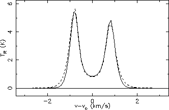

 Line profiles for HCO+ (solid) and H
 Line profiles for CS 5
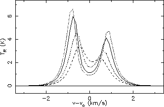 Line profiles for different abundances of HCO+ 4
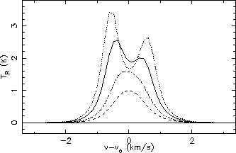 Line profiles for different abundances of CS 5
![\includegraphics[scale=0.57]{buk2.eps}](img1098.gif) Output of Buckley's model results (taken from [7]) for different abundances
Output of Buckley's model results (taken from [7]) for different abundances
 Line profiles for HCO+ 3
 Line profiles for HCO+ 4
 The other unique feature of the ASTRA program is the ability to change the cloud viewing angle. Clearly this is
not a useful feature for a spherically symmetric cloud. However, the spherically symmetric cloud model can be used
to check the basic working of this feature. For a spherically symmetric cloud the line profiles should be the same
no matter where they are viewed from. Figure 5.28 shows the line profiles for the cloud at 0