Next: Radiative Transfer Modelling
Up: Methods for Reducing Telescope
Previous: Correcting the Temperature Scale
Rotation Diagrams
Where observations have been taken of more than one transition for a given molecule then a standard
technique can be used to find the column density, namely the use of rotation diagrams. It can easily be shown
that provided a source is optically thin
 |
(2.31) |
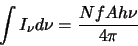
since the total intensity detected,
 ,
is equal to the number of
molecules in the line of sight in a unit area,
,
is equal to the number of
molecules in the line of sight in a unit area,  (ie. the column density),
times the fraction of the population in the upper state of the transition,
(ie. the column density),
times the fraction of the population in the upper state of the transition,  ,
times the
Einstein A coefficient,
,
times the
Einstein A coefficient,  ,
( ie. the spontaneous decay rate) times the energy released per
decay ,
,
( ie. the spontaneous decay rate) times the energy released per
decay , ,
divided by the surface area of a unit sphere,
,
divided by the surface area of a unit sphere,  .
.
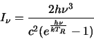
 is the
radiation intensity and for a black body is given by
is the
radiation intensity and for a black body is given by
which in the Rayleigh-Jeans approximation (
 )
reduces to
)
reduces to
 |
(2.32) |
The temperature  is the radiation temperature and is defined by this
equation. As such it applies only to a specific value of
is the radiation temperature and is defined by this
equation. As such it applies only to a specific value of  and may be different for
a different value of .
Substituting equation 2.34 into
equation 2.33 and
changing the integration to be over
and may be different for
a different value of .
Substituting equation 2.34 into
equation 2.33 and
changing the integration to be over  (ie. use
 )
yields
)
yields
 |
(2.33) |
The Einstein A coefficient,
can now be substituted in along with the LTE assumption that all the s are equal to a single
rotation temperature,  .
The
.
The  is the rotational degeneracy of the upper
level, S is the intensity of the transition and
is the rotational degeneracy of the upper
level, S is the intensity of the transition and  is the appropriate dipole moment
for the transition. The LTE assumption implies that
is the appropriate dipole moment
for the transition. The LTE assumption implies that
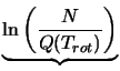
where Q is a function of
and is termed the partition
function,  and
and  are the reduced nuclear spin and K-level degeneracies
respectively. All this, when substituted into equation 2.35 leads to
are the reduced nuclear spin and K-level degeneracies
respectively. All this, when substituted into equation 2.35 leads to
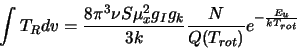 |
(2.34) |
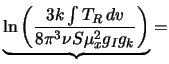
This can then be re-arranged and logarithms2.7 taken to finally yield an equation of the form:
For a list of formulae for
 see Blake et al. [6] or Turner [33], for linear diatomic
molecules the formula is simple
see Blake et al. [6] or Turner [33], for linear diatomic
molecules the formula is simple
but for non-linear molecules it is rather more complex, for example, for CH OH :
OH :
All the values in x and y are known so a point can be plotted on a graph for
each detection and a straight line fitted. The slope of the line is then  ,
from which T
,
from which T is then known and the y-axis intercept is
  ,
from which
is then known.
,
from which
is then known.
Those molecules with only 1 or 2 detections can have a lower limit placed on their column
density via a method based on the same theory as the rotation diagrams. A
rearrangement of the standard equation for a rotation diagram (equation 2.37 above) yields:
As long as a value for T
is
known this can be solved. Unfortunately a value for T
is often not known
with any accuracy and this is the main source of error for molecules that are
genuinely optically thin. As a first approximation
 is used for molecules that are either
symmetric or only slightly asymmetric.
is used for molecules that are either
symmetric or only slightly asymmetric.
The main problem with this method is that it requires the molecule to be optically thin in all the transitions
used. If this is not the case then it is impossible to be certain by any simple method of the column density. However
for an optically thin cloud it provides a useful quick method of finding the column density. In a cloud where
little or no previous data is available this could be used to provide a starting point for trying more
sophisticated modelling.
Next: Radiative Transfer Modelling
Up: Methods for Reducing Telescope
Previous: Correcting the Temperature Scale
1999-04-12
![\begin{displaymath}Q(T_{rot})=2\left[ \frac{\pi (kT_{rot})^3}{h^3ABC} \right] ^{\frac{1}{2}}
\end{displaymath}](img285.gif)